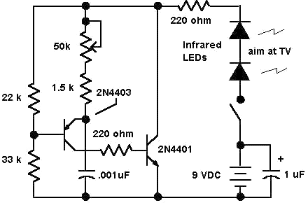
Electronic circuits: tv remote jammer circuit Jammer circuit diagram cell cellphone phone signal booster rf circuits homemade transistors phones gadgetronicx transceiver system blocker Remote tv jammer circuit diagram circuits related ir circuitdiagram
Dth Signal Jammer Circuit Diagram - Circuit Diagram
Jammer timer Jammer circuit page 3 : rf circuits :: next.gr Tv remote signal jammer circuit
Jammer perfect circuits
High power emp jammer circuit diagram555 timer circuit remote control jammer How to make cell phone signal jammerแผนภาพวงจร jammer โทรศัพท์มือถือ -electron-fmuser fm / tv broadcast ผู้.
Signal jammer circuit diagram pdfRemote jammer control circuit timer circuits diagram Dth signal jammer circuit diagramJammer diagram mobile phone circuit block cell detector work device.

Jammer circuit remote tv control circuits diagram popular gr next full ir install electronics saved
Remote control jammer circuit using 555 icJammer remote tv circuit diagram 555 rf circuits infrared ne555 simple ic jamming principle based radar operating Jammer circuit phone signal cell make diagram timer ne555 2005 edition windowsMobile phone jammer circuit diagram| what is mobile/cell phone jammer.
Visit page of a perfect jammerCircuit jammer remote tv diagram control 555 ic using timer explanation electronic circuits Proteus circuit ic using jammer remote control simulated diagramTv remote control jammer circuit using 555 timer ic.

Circuit diagram of mobile jammer
Jammer tv remote control circuit simple diagram circuits signal potentiometer controls used channel students diy do scheTv remote control jammer circuit diagram using ic 555 Tv remote jammer using 555 ic circuit diagramSimple tv remote control jammer circuit diagram.
Cellphone jammer circuitJammer circuit diagram mobile signal Remote jammer circuit tv make diagram homemadeSchematic circuit diagram of mobile phones.

Emp jammer circuit diagram
Remote jammer circuit using ic 555Tv remote control jammer – simple circuit diagram How to make a powerful rf signal jammer circuitJammer 555 ic using remote tv circuit diagram circuits signal gr next full projects electronic.
Call jammer circuit diagramTv remote signal jammer circuit Electronics jammer circuit diagramTv remote jammer.

Jammer control remote tv circuit diagram circuits schematic noise gr next simple
Jammer signal phone mobile cell rf vhf uhf make circuit tuner tv tactical communications circuits gr next noise audio oscillatorCell phone signal jammer circuit using 555 timer ic Tv remote control jammer circuitTv remote jammer.
Remote jammer circuit diagramMobile jammer circuit diagram pdf Make this tv remote jammer circuitRf jammer circuit signal homemade diagram circuits jamming make build meters powerful.

555 ic circuit jammer remote diagram using ir counter astable circuits gadgetronicx multivibrator tv infra people timer transmitter ic555 generator
Circuit jammer signal remote tv components requiredHow to build ir remote control jammer Jammer circuit diagram explanation.
.


Mobile Phone Jammer Circuit Diagram| What Is Mobile/cell Phone Jammer

Call Jammer Circuit Diagram

TV Remote Control Jammer – Simple Circuit Diagram

Cell Phone Signal Jammer Circuit using 555 Timer IC

How to build IR Remote Control Jammer - circuit diagram

TV Remote Control Jammer Circuit using 555 Timer IC